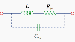
The Inductor Impedance Calculator is a tool that can calculate Impedance of a coil on one click. The The impedance of an inductor is a measure of its opposition to alternating current (AC) flow, similar to resistance, but it takes into account both the resistance and reactance of the inductor. Impedance is a complex quantity that incorporates both magnitude and phase information.
Inductor Impedance Calculator
The impedance (ZL) of an inductor is calculated using the following formula:
ZL = R + jωL
Where:
- ZL is the impedance of the inductor in ohms (Ω).
- j is the imaginary unit, representing a phase shift of 90 degrees.
- ω (omega) is the angular frequency of the AC signal in radians per second (rad/s).
- L is the inductance of the inductor in henrys (H).
- R is the Resistance of the Coil.
- Neglect the value of Capacitance for this calculation.

Key points to understand about inductor impedance:
- Complex Quantity: Impedance is a complex quantity that has both real and imaginary components.
- Angular Frequency: The angular frequency (ω) is related to the frequency (f) of the AC signal by ω = 2πf.
- Magnitude and Phase: Impedance has both magnitude and phase information.
- Units: Impedance is measured in ohms (Ω), the same unit as resistance.
- Ohm’s Law for AC: Ohm’s Law for AC circuits is modified to include impedance: V = I * Z.
- Phase Shift: The voltage across an inductor lags behind the current by 90 degrees in an ideal inductor.
- Reactance and Resistance: The impedance (Z) can be broken down into its real part (resistance) and imaginary part (reactance) using the equation Z = R + jX.
In summary, impedance in an inductor combines both resistive and reactive effects, accounting for the opposition to AC current flow and the phase shift between voltage and current. Impedance is a fundamental parameter in AC circuit analysis and design.
Read: