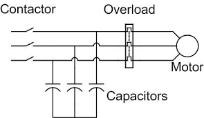
Power Factor Correction Capacitor Bank Calculator is a tool that will help you to get the required capacitor bank rating for raising the Power Factor of the system. Improving the power factor of a system using a capacitor bank is a common practice in electrical engineering, particularly in industrial and commercial applications. A poor power factor, either lagging or leading, can result in inefficient power usage and higher electricity costs. To enhance the power factor and make electrical systems more efficient, a capacitor bank is often employed.
Power Factor Improvement Calculator
| Parameter | Value |
|---|---|
| Required Change in Reactive Power (ΔQ) | [Calculated Value] kVAR |
| Number of Capacitors Required | [Calculated Value] |
1. Understand Power Factor: Before implementing any power factor correction, it’s crucial to understand what power factor (PF) is. Power factor is the ratio of real power (in watts) to apparent power (in volt-amperes) in an AC electrical system. It is a dimensionless number that ranges from 0 to 1, and it quantifies how effectively electrical power is being converted into useful work. A power factor of 1 (or 100%) indicates perfect efficiency, while a lower power factor implies energy losses.
2. Determine the Existing Power Factor: Measure or determine the existing power factor of the system. This is often done using power meters or power analyzers. The power factor can be lagging (usually inductive loads like motors) or leading (typically capacitive loads).
3. Set a Target Power Factor: Decide on the target power factor you want to achieve. Most utility companies provide guidelines or specify a minimum power factor requirement. Common target values are 0.95 or 0.99 lagging.
4. Calculate Required Reactive Power (Qc): Calculate the required change in reactive power (Qc) using the following formula:
- For lagging power factor (most common): Qc = P * (tan(θ1) – tan(θ2))
- For leading power factor: Qc = P * (tan(θ2) – tan(θ1))
Where:
- Qc: Required capacitive reactive power (in volt-amperes reactive, VAR)
- P: Real power (in watts)
- θ1: Existing phase angle between voltage and current
- θ2: Desired phase angle for the target power factor
5. Select Capacitor Banks: Choose the appropriate capacitor banks to provide the required reactive power (Qc). Capacitors come in various sizes, typically specified in kilovolt-amperes reactive (kVAR). Consider the voltage rating, number of capacitors, and their kVAR ratings.

6. Connect Capacitor Banks: Install the selected capacitor banks in parallel with the load that needs power factor correction. The capacitors should be connected to the same electrical bus as the inductive or lagging load.
7. Monitor and Adjust: Once the capacitor bank is operational, closely monitor the power factor using power meters or monitoring systems. Adjust the number of capacitors or their settings to fine-tune the power factor and ensure it aligns with the desired target.
8. Ensure Safety and Compliance: Safety is of utmost importance when working with electrical equipment. Ensure that the installation complies with safety standards and regulations. Capacitor banks should be properly fused and protected against overvoltage or overcurrent conditions.
9. Maintenance: Regularly inspect and maintain the capacitor bank. Check for damaged capacitors, loose connections, or any signs of wear. Maintenance ensures that the power factor correction system remains effective.
By adding capacitors to the system, you are effectively introducing a leading reactive power component that offsets the lagging component caused by inductive loads. This helps to bring the power factor closer to unity (1) and reduces the losses associated with poor power factor, resulting in energy savings and improved system efficiency.
Thanks for reading the post on Power Factor Correction Capacitor Bank Calculator.