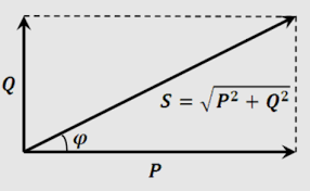
If you are looking for the ways to calculate the Active Power, Reactive Power, and Apparent Power using line voltage and line current data, you are at the right page. The Reactive Power Calculator is designed to calculate all the three components using the input data of the line.
Power Calculation
| Parameter | Value | Unit |
|---|---|---|
| Line Voltage (Vline) | Volts (V) | |
| Line Current (Iline) | Amperes (A) | |
| Power Factor (PF) | Decimal (0.00 to 1.00) | |
| Active Power (P) | - | kW |
| Reactive Power (Q) | - | kVAR |
| Apparent Power (S) | - | kVA |
How the Reactive Power Calculator Works?
Active (Real) Power (P)
To calculate active power (P) in a three-phase system using line voltage (Vline) and line current (Iline), you can use the formula:P = √3 * Vline * Iline * PF
- √3 is the square root of 3 (approximately 1.732).
- Vline is the line-to-line voltage (the voltage between two phases).
- Iline is the line current (the current flowing through one phase of the circuit).
- PF is the power factor, which is calculated based on the phase angle between Vline and Iline.
The power factor (PF) is still calculated as the cosine of the phase angle (φ) between Vline and Iline:
PF = cos(φ)

Reactive Power (Q)
To calculate reactive power (Q) in a three-phase system using line voltage and line current, you can use the formula:Q = √3 * Vline * Iline * sin(φ)
-
- √3 is the square root of 3.
- Vline is the line-to-line voltage.
- Iline is the line current.
- φ (phi) is the phase angle between Vline and Iline.
Apparent Power (S)
To calculate apparent power (S) in a three-phase system using line voltage and line current, you can use the formula:S = √3 * Vline * Iline
-
- √3 is the square root of 3.
- Vline is the line-to-line voltage.
- Iline is the line current.
What is a Three Phase System?
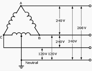
A three-phase system is a type of polyphone electrical system commonly used for generating, transmitting, and distributing electric power. It consists of three separate conductors, typically labeled as Phase A, Phase B, and Phase C, each carrying an alternating current (AC) waveform. These waveforms are identical in frequency but have a phase difference of 120 degrees (or one-third of a cycle) between them.

Variables in Three Phase System
- Three Phases: In a three-phase system, there are three separate phases or circuit conductors. Each phase carries an AC voltage or current that varies sinusoidally over time.
- Phase Difference: The AC waveforms in a three-phase system are 120 degrees out of phase with each other. This phase offset ensures that at any given time, one of the phases is at its peak value while the others are at intermediate points in their cycles. This phase separation results in a smoother and more continuous power delivery compared to single-phase systems.
- Balanced Load: In ideal conditions, a three-phase system is balanced, meaning that the loads on each phase are equal, and the voltages are also balanced. This balance is crucial for efficient and reliable operation.
- Efficiency: Three-phase systems are more efficient for power transmission and distribution over long distances compared to single-phase systems. They require fewer conductors and can deliver a higher amount of power with less voltage drop.
- Applications: Three-phase systems are commonly used in industrial and commercial applications, such as factories, manufacturing plants, and large machinery. They are also used for electrical distribution in residential areas, especially in regions with a high demand for power.
- Motor Operation: Three-phase AC motors are widely used because they are more efficient and provide smoother torque compared to single-phase motors. They are commonly found in industrial equipment, appliances, and HVAC systems.
- Voltage Levels: The standard voltage levels for three-phase systems can vary by region, but common values include 208V, 240V, 415V, 480V, and 600V in North America, with higher voltages used for industrial and utility applications.
- Phases in Generation and Distribution: Electricity is often generated and distributed in a three-phase system, especially in large power plants and high-voltage transmission lines. Transformers are used to step up or step down the voltage levels as needed for different stages of distribution.
- Color Coding: In some countries, color-coding is used to identify the three phases in wiring. For example, Phase A may be identified with brown or black, Phase B with gray or red, and Phase C with blue.
In summary, a three-phase system is a fundamental electrical configuration used for efficient power generation, transmission, and distribution. Its balanced and phased nature allows for more consistent power delivery and greater efficiency, making it well-suited for various industrial, commercial, and residential applications. The adjustments for a three-phase system involve multiplying the line voltage and line current by √3 to account for the square root of 3 factor. This factor arises because in a three-phase system, the power is distributed across three phases, and the line voltage represents the voltage between two phases rather than a single phase. The power factor (PF) and the phase angle (φ) calculations remain the same as in the previous explanation.
Thanks for reading the Reactive Power Calculator.